Physical Installation of EnvisaLink 4 onto Vista 20p Panel
Moderators: EyezOnRich, GrandWizard
-
nutshellml
- Posts: 8
- Joined: Fri Mar 11, 2016 11:42 am
Physical Installation of EnvisaLink 4 onto Vista 20p Panel
Morning all... received my EVL4 and looking to install/mount it onto my Honeywell Vista 20p panel, but the holes don't seem to line up anywhere, I can only fit one with the plastic mounting knob included with the EVL4. I don't want to use only one as it's not too secure and "flops" around. Any thoughts? Photos on EVL4 installed on the panel or advice on how to do it? THANKS!!
Re: Physical Installation of EnvisaLink 4 onto Vista 20p Pan
I had the same issue when I installed it earlier this week. I just used the 2-way tape that came in the box.
Re: Physical Installation of EnvisaLink 4 onto Vista 20p Pan
I just drilled 2 extra holes on the left side wall of the Honeywell cabinet for the standoffs and mounted it there.
-
GrandWizard
- Posts: 2375
- Joined: Tue Nov 16, 2010 4:08 pm
Re: Physical Installation of EnvisaLink 4 onto Vista 20p Pan
The EVL4 includes a strip of two-way tape foam for Honeywell users. I would recommend you use that.
Re: Physical Installation of EnvisaLink 4 onto Vista 20p Panel
I thought about drilling the holes until I saw the tape. I put the tape on, but then I saw the tape isn't very thick and the solder wires stick out the back almost as far as the tape is thick. I got out an ohm-meter and verified that these solder joints are connected to the devices on the top and should not be grounded on the panel. For example, if the pins on the back touch the panel side, it would be like the bare Red, Black, Yellow, and Green wires touching the side of the panel, which I assume is a bad thing. The paint appears to be insulating, but I wouldn't count on that as a long term solution.
Anyone have ideas other than drilling holes? What size holes did you drill? I'm thinking 3/16". Otherwise, I'm thinking about mounting an insulator to the side of the panel like a block of wood. I have an electrical engineering friend who might be able to tell me if that's a good idea.
Anyone have ideas other than drilling holes? What size holes did you drill? I'm thinking 3/16". Otherwise, I'm thinking about mounting an insulator to the side of the panel like a block of wood. I have an electrical engineering friend who might be able to tell me if that's a good idea.
-
narrowfoot
- Posts: 1
- Joined: Wed Mar 22, 2017 1:17 pm
Re: Physical Installation of EnvisaLink 4 onto Vista 20p Panel
look into "adhesive standoffs"
Re: Physical Installation of EnvisaLink 4 onto Vista 20p Panel
I don't much trust adhesive "anchors," so I rounded-up some nylon stand-offs, matching screws, etc., and did this:
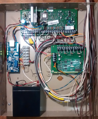
(That's before the job was complete. Yeah, I like BIG service loops .)
.)
The board on the right is a zone expander. The terminal strip next to the EVL4 is for the auxiliary connector in the middle of the Vista 20P board. I'm using the power connections from that for my wired motions and, to reset my 4-wire smoke & fire, one of the switched outputs.
I purposely left room in the lower-right for another zone expander--just in case.
(That's before the job was complete. Yeah, I like BIG service loops
The board on the right is a zone expander. The terminal strip next to the EVL4 is for the auxiliary connector in the middle of the Vista 20P board. I'm using the power connections from that for my wired motions and, to reset my 4-wire smoke & fire, one of the switched outputs.
I purposely left room in the lower-right for another zone expander--just in case.